
Primary Interface
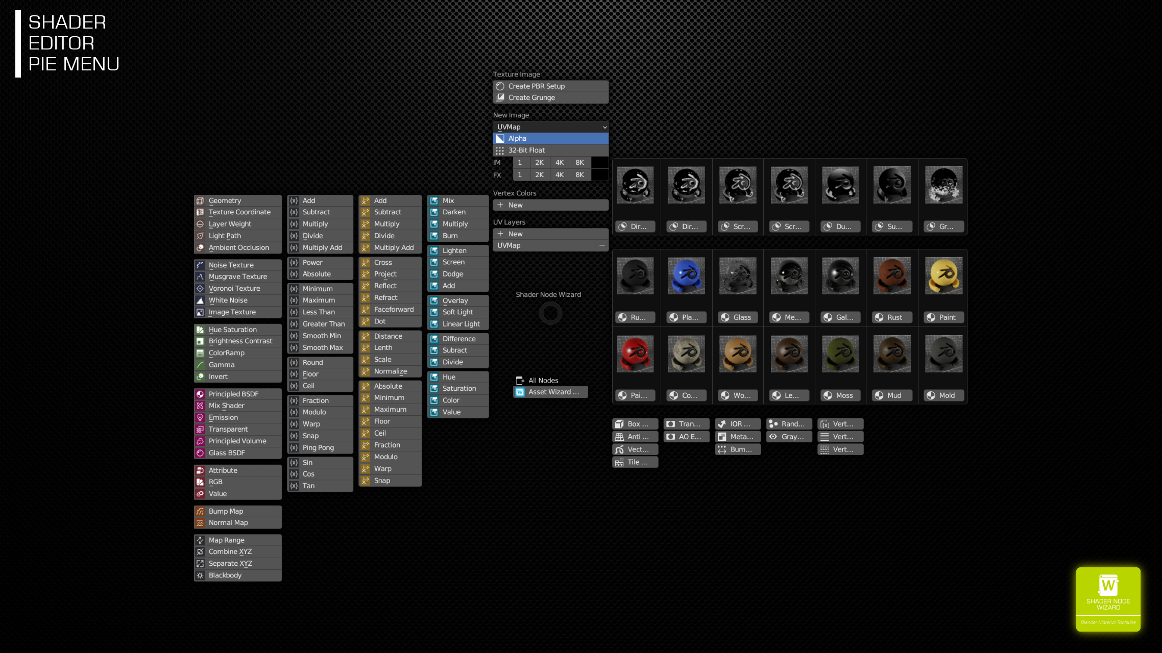
The main Pie Menu shows up by pressing the D-Key inside Material Shader Editor. Besides that, there’s a Shader Node Wizard side menu with some additional tools.
Common Standard Nodes
This area is a quick access to most common nodes. They were dropped like any other node selected with Shift-A. The second, third and fouth column contains Math, Vector Math and MixRGB node, respectively. By selecting one of those, the chosen operation or mix types is automatically active after drop.
Create PBR Setup and Create Grunge
This opens a second Pie Menu, where you can choose the respective Image Folder and upon selection, an image browser to select the PBR Set or Grunge Texture. A Node Group with the selected Texture is created, which can be placed in your Node Tree.
In case of PBR Sets, the Inputs and Outputs are taylored to the available PBR channels and allow adjustment to those. Grunge Textures have both a Value and Normal Output. The Normal Output is the Bump Map created from the Grunge Map. Inputs allow adjustments to both Value and Normal result.
New in version 1.2, using the ExtremePBR Vault library, SNW detects available texture resolutions. You can than select the resolution you want on creation (0.5K-8K), or adjust it in the edit dialog as well.
PBR Nodes
These nodes manage complete PBR sets, which can be found online on various platforms. Inputs and outputs partially depend on the available channels. For example, the AO input is available if the set contains an AO file.
Always remember, hitting the edit shortcut button (default: E-Key) when you’ve selected the Grunge Node, lets you change the grunge file.
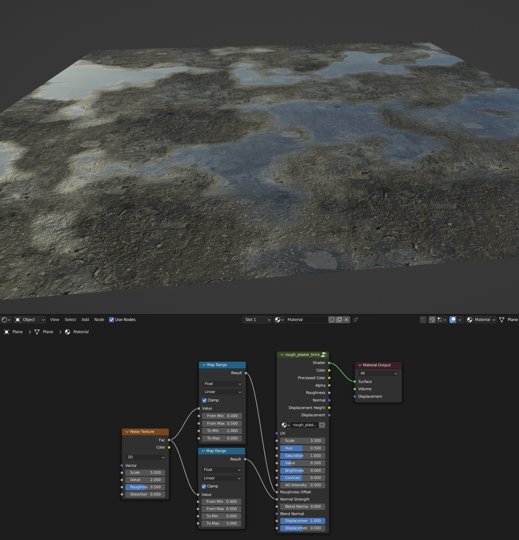
The image above shows a simple way to create noise based puddles by affecting the Roughness Offset and Normal Strength, setting Roughness Offset to -1.0 and Normal Strength to 0.0 were the water should be.
Inputs:
- Scale: Uniform scaler to the incoming or internal UV map.
- Hue, Saturation, Value: The diffuse map is passed through a HSL Node, these are the controls.
- Brightness and Contrast: After the HSL Node, the Diffuse is passed through and Brightness Constrast Node.
- AO Intensity*: Intensity of the AO map.
- Roughness Offset: This value is added to the roughness map value and clamped. Useful to simulate wetness.
- Normal Strength: Just wired to the Strength input of the Normal Map / Bump Map Node.
- Blend Normal Weight and Blend Normal: The Blend Normal Input can be used to mix the PBR Normal with a different Normal. Bump Normal Weight is the weight factor between both Normals. 0.0 just uses the internal Normal, 1.0 the Blend Normal. See Grunge Nodes below for a use case.
- Emission Strength*: If an emission map is part of the set, this controls the strength.
- Displacement Intensity and Displacement Midlevel*: If a displacement map is available, this controls the generated Displacement Vector.
* These are available only, if the map is present in the set. When updating the set (E-Key) and the new set has those maps, inputs were added (or removed if channel isn’t available).
Outputs also depend on the available maps in the set. They are passed from from the maps. These are sometimes very useful to combine them with other nodes. For example the Normal can be used as Blend Normal. Think of a painted, but rusted surface. The rust normal may partially affect the painted surface.
Grunge Nodes
Some tools built around a single gray image texture. The node builder recognizes 4 channel packed gray images if the image name ends with -4g, and allows to create a grunge node from R, G, B and A channel. Grunge files included to SNW use this technique. This saves GPU memory in case you used Grunge files from the same pack.
Always remember, hitting the edit shortcut button (default: E-Key) when you’ve selected the Grunge Node, lets you change the grunge file.
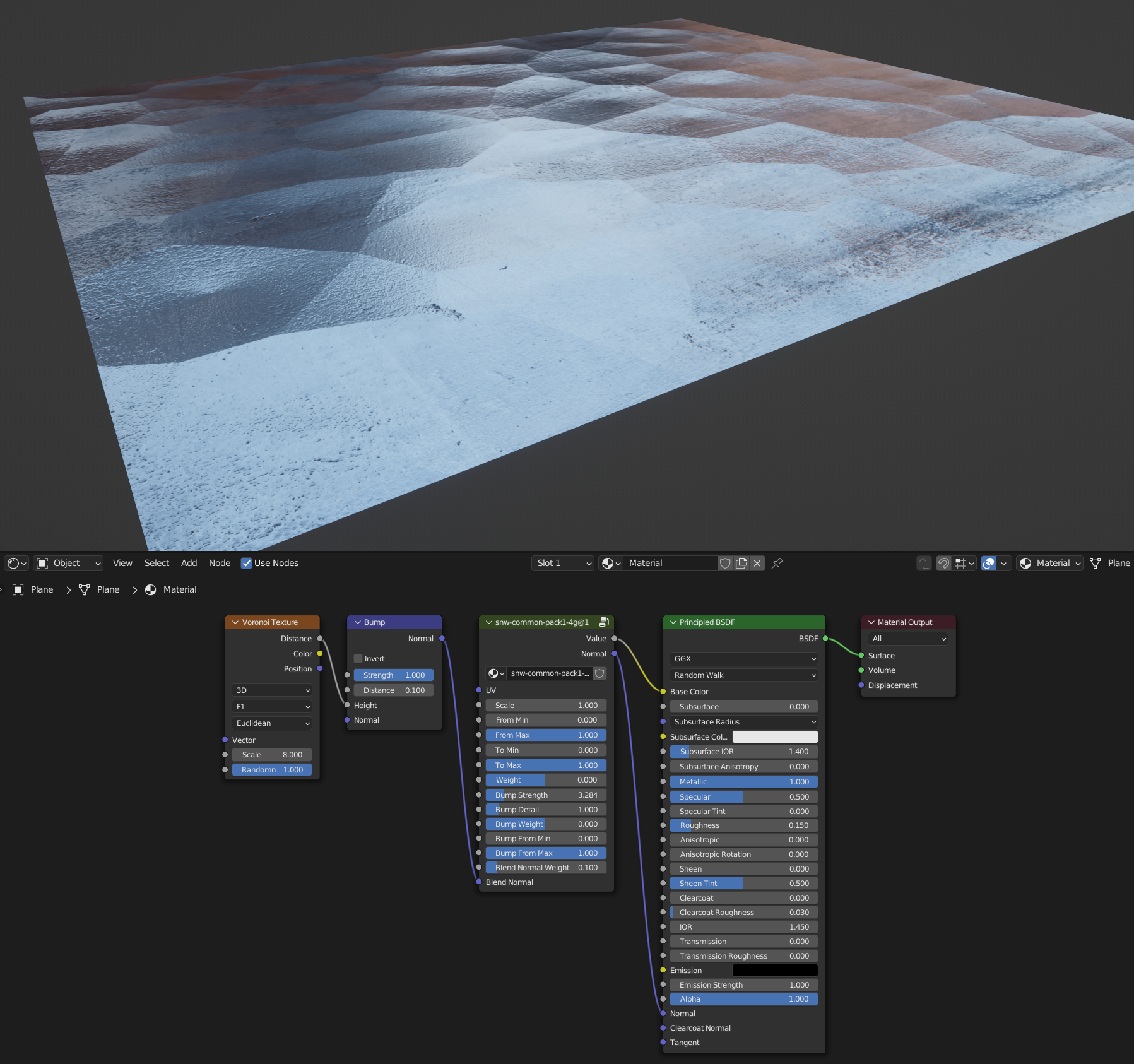
Grunge Nodes have several useful features. They have both a Value and Normal output. In the image above, this is wired to a Principled BSDF with Metallic=1.0 and Roughness=0.1 for better Normal visualization. In the image above, a Voronoi based bump is used to show the Blend Normal feature.
Inputs:
- Scale: Uniform scaler to the incoming or internal UV map.
- From Min, From Max, To Min and To Max: Just the wired sockets from a Map Range Node that is put between the grunge texture and the value output.
- Weight: After passing the gray value through the Map Range Node, a Math Power Node is placed and Weight controls the exponent. To get finer control of the exponent < 1, Weight converts the value, so you have a more linear control (-N <-> +N). See table below.
- Bump Strength: Just the Strength of the used Bump Map Node.
- Bump Detail: Is a factor that effects the Distance input of Bump Map Node. On creation, the Grunge Texture Size is used to calculate the distance from pixel to pixel, which is than multiplied by this factor. Play with it.
- Bump Weight: Identical to Weight, just for the Normal Output.
- Bump From Min and Bump From Max: The respective inputs from the Map Range Node placed in front of the Bump Map Node, so you can select the gray levels used to create the Normal Map. Set Min to 1.0 and Max to 0.0 to invert the Bump Effect.
- Blend Normal Weight and Blend Normal: The Blend Normal Input can be used to mix the generated Normal with a different Normal, as shown in the image above. Bump Normal Weight is the weight factor between both Normals. 0.0 just uses the internal Normal, 1.0 the Blend Normal.
| Weight Value | Exponent |
| 0 | 1 |
| > 0 | Weight + 1 |
| < 0 | 1 / (Weight + 1) |
Texture Node Edit Dialog
Hitting E-Key when a PBR or Grunge node is selected (or a node group up to one level above) opens the edit dialog which shows up to 8 texture settings to edit. It contains many settings that let you switch textures, mapping, anti-repeat settings and interpolation.
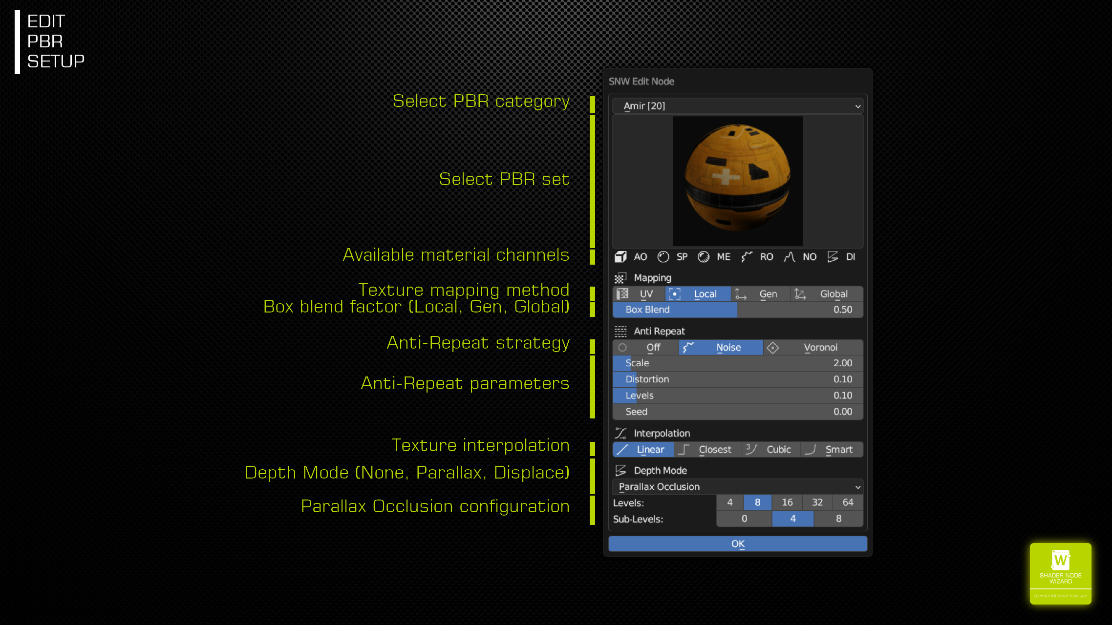
- Change Texture Category/Change Texture: Select a different PBR Set/Grunge Texture
- Available Channels: Just for PBR Sets, displays which channels are available
- Texture Mapping:
- UV: Use primary UV channel, or, if connected the Node’s UV input
- Local: Box/UVW mapping, using Object output from Texture Coordinate node
- Gen: Box/UVW mapping, using Generated output from Texture Coordinate node
- Global: Box/UVW mapping, uses same as Local mapping, but adds object Position.
- Anti-Repeat: Choose one of the Anti-Repeat strategies if texture repetition is visible.
- Off: Disabled
- Noise: Noise pattern based strategy. Slices noise pattern into levels and assign different offsets to each level.
- Voronoi: Voronoi pattern based strategy. Uses random color from pattern as offset in the specific cell.
- Texture Interpolation: Select the interpolation mode of the used for texture lookup. If Eevee shows artifacts using Anti-Repeat, try Cubic/Smart mode here.
See how to switch to global mapping and enable Anti-Repeat.
New Image
This has been enhanced starting from version 1.1. The generated images are intended to paint on, which SNW helps you in various aspects.
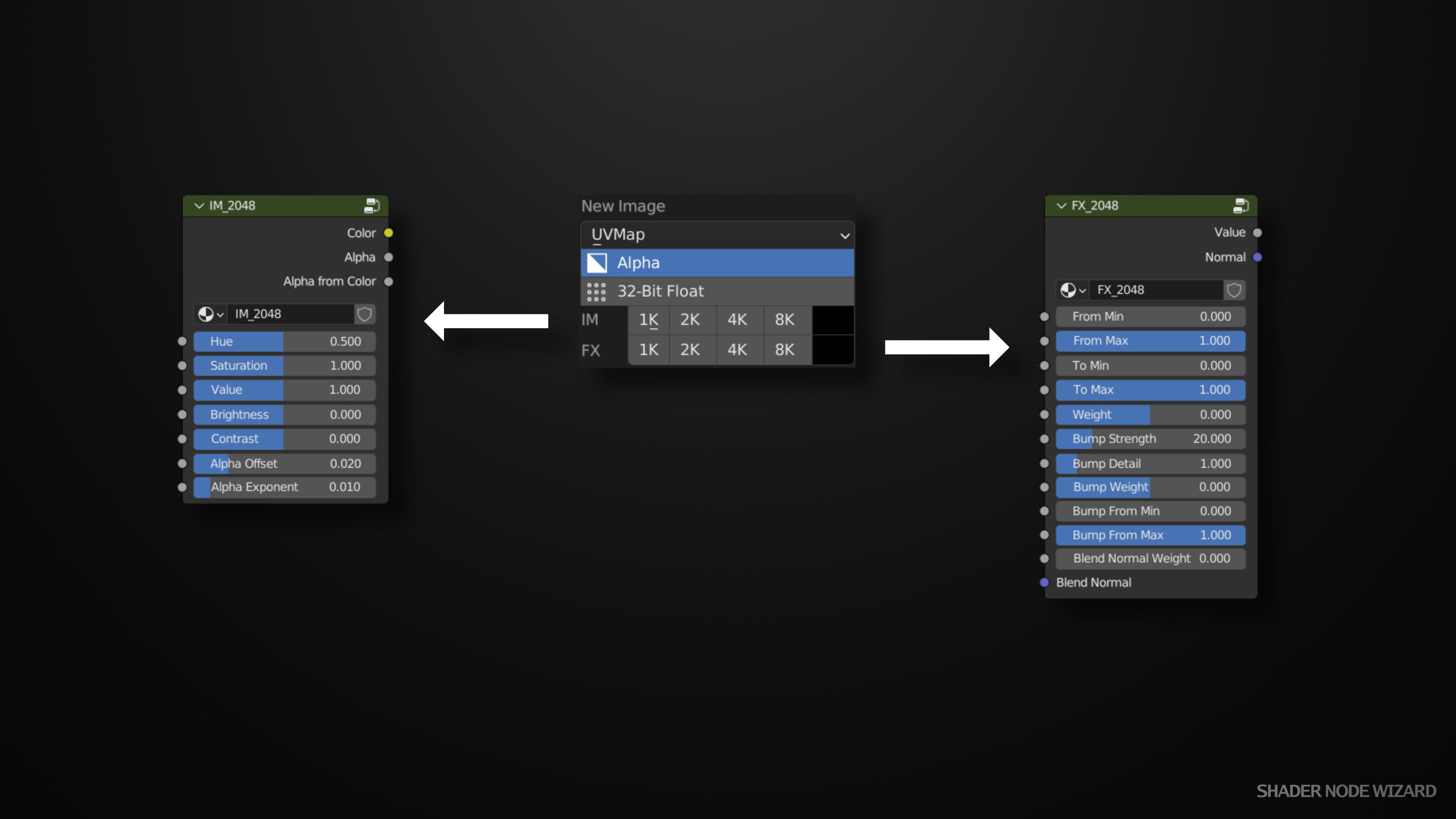
UVMap, Alpha, 32-Bit Float and the color just right to the resolution are self explaining, these are just parameters used to create the image. UVMap takes a special role. If you use different UVMaps for different images and use SNW to switch between the images you paint on, SNW automatically adjusts the UVMap used for painting.
If you click on one of the resolutions, a new image and the corresponding Node is generated and can be placed in your node tree. The upper row (IM) creates the node on the left side, while the lower row (FX) the one on the right side. Internally, the image is identical, just a blank image. But SNW creates some processing around the image, which can be controlled using the inputs.
IM Images
They are just color images, useful to add as decals to your other nodes. You can control Hue, Saturation, Value, Brightness and Contrast quite easily. One additional feature is the automatic alpha generation. Areas of the image which are (close to) black are than expected as transparent. The Alpha Offset and Alpha Exponent inputs can be used to tweak the level. The generated alpha mask is available at the Alpha from Color output.
FX Images
Those are quite similar to grunge maps, inputs are almost identical to grunge nodes, see the description above. These maps are very useful to create masks or faked geometry using the Normal output and typical hardsurface alpha brushes.
See it in action:
- Upper left: FX Image, Normal output in inversed, so the bump looks like engraved, Value output is used to darken the wood PBR.
- Upper right: FX Image, Normal output is used as is as Blend Normal to a Metal Node to create faked hard surface details. A second FX Image is used as mask between the Metal Node and an Emission Shader (Fac in Mix Shader).
- Lower left: IM Image, Color output is used as Base Color in a Principled BSDF. The Alpha from Color output is multiplied with an additional Grunge texture to create a worn look. The Normal to the Principled BSDF comes from the wall PBR node, to let the grafitti look like affected by the wall structure, finally the wall PBR is mixed with the Principled BSDF, using the worn looking mask coming from the Alpha channel.
- Lower right: FX Image, just simple mask between the green painted PBR and a Black colored Principled BSDF, with low roughness, using the Normal from the FX Image, so the leak gets more structure.
Vertex Colors
Vertex colors, or specifically face colors play an important role to assign different properties to faces in a single mesh and material. SNW has several tools to make usage quite easy.
You can create multiple Vertex Color Nodes from the middle of the Pie menu and use them as usual. But SNW gives them special roles. Combined with these 3 Nodes, you can simply set values, colors or shaders for specific faces.
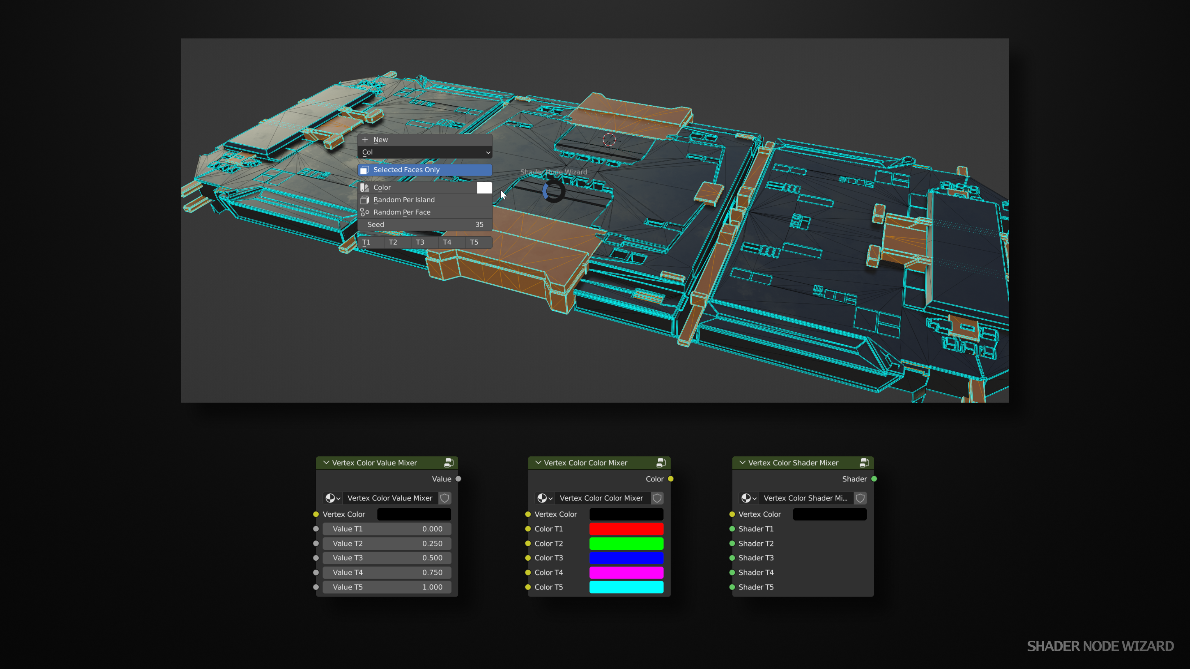
When you are in Edit Mode, you can open the Vertex Color Pie using the hotkey (default: D-Key). From there you have several options:
- New: Create a new Vertex Color. It is automatically selected for adjustments. But you can always switch with the control below the New button.
- Selected Faces Only: All operations below just affect the selected faces.
- Color: Sets the color to the one selected right to this button.
- Random Per Island: Similar to cycles Random Per Island feature, assigns a random color to every separated part of the geometry.
- Random Per Face: As the name suggests, every face in the mesh will get a random color.
- Seed: Affects the generated colors for both operations above.
- T1-T5: These are intended to work with the 3 nodes in the lower part of the image. Internally, assigns 5 different levels of gray to the faces and the nodes splits these color information and pass through the value, color or shader depending on the selected gray level.
Vertex Color Value Mixer: Helpful to define e.g. different roughness, value, saturation to different areas of the mesh.
Vertex Color Color Mixer: Assign these colors to specific areas.
Vertex Color Shader Mixer: Manage different Materials in a single Node Tree and assign them to different parts of the mesh.
One might think, the first 2 nodes (Value and Color) are useless, as you can directly pass the values to the following node graph, but I think it’s more comfortable to tweak these values here instead of always reassign colors until a desired result has been reached.
FX
Painted Metal
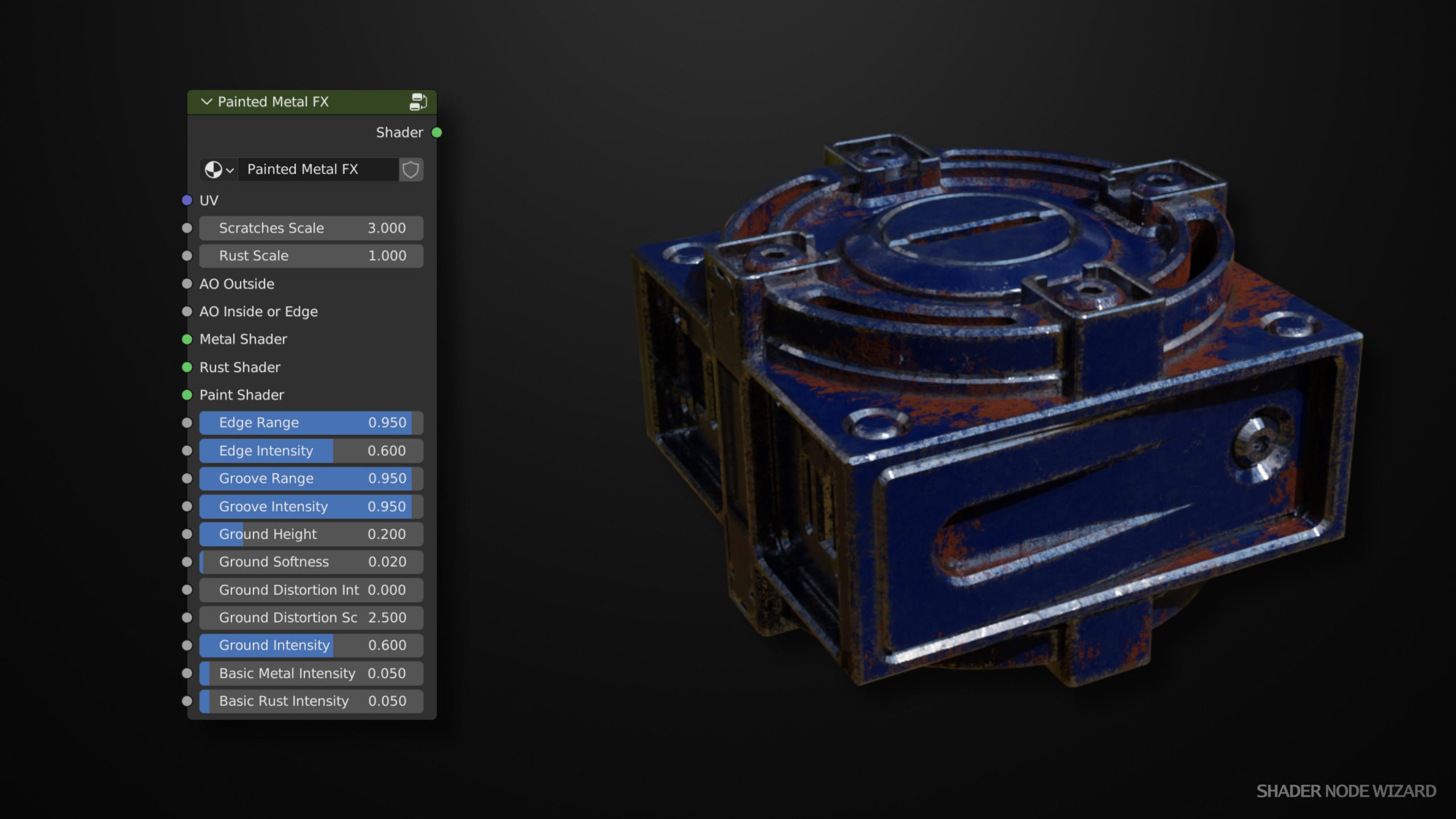
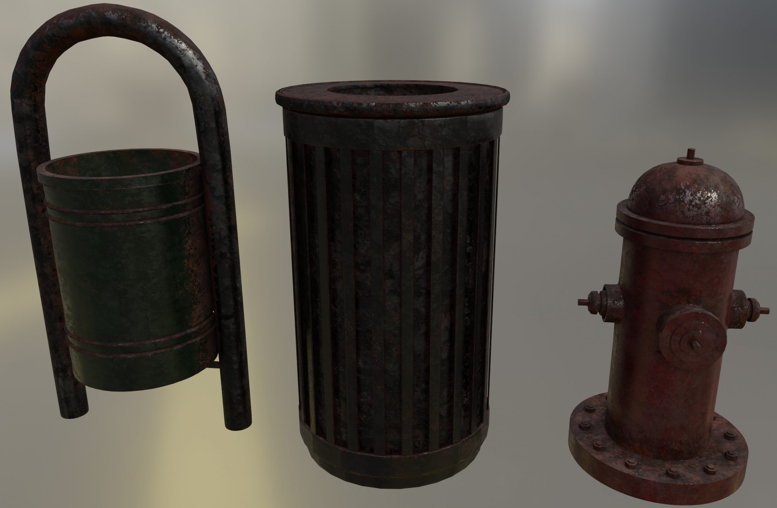
This FX combines 3 shaders using adjustable masks to a final material. The masks require AO/Edge information, which must be supplied from a baked mask or from the AO Edge (Cycles) Tool node. Baked masks are faster, get better results and work well in Eevee.
The idea is to have 3 layers. Metal at the lowest level, rust above and finally a paint layer on top of it. Metal occurs on the white areas from the AO Inside or Edge Input. It’s is than adjusted with the Edge Range and Edge Intensity inputs and masked to the Scratch Grunge which resides in this node group. Rust will be more visible in areas that are white from the AO Outside input (inside areas), adjusted by the Groove Range and Groove Intensity inputs. Besides that, as rust tends to be more present in wet areas, which often is on the base of an object, the Ground Inputs adjust the rust presence from bottom to top. Basic Metal Intensity and Basic Rust Intensity adjust the general level of metal and rust.
Scratches Scale and Rust Scale control the both grunge maps inside this node, which are used to create irregular looking occurences. You can change these maps by pressing the E-Key when the node is selected.
Worn
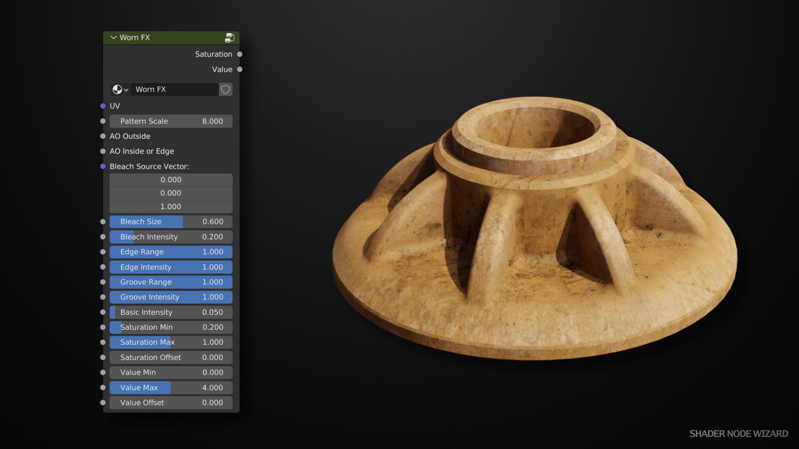
This node is intended to calculate Saturation and Value values, that must be connected to the material. The effect should make materials looking older and used. It finally helps to make materials looking less even colored and lighted. There are primary 3 areas, where this occurs.
- Sun Bleaching: These should simulate color bleaching by the sun. If materials have a long time in the sun, there colors loose intensity. So the Bleach Source Vector (default to up) adjusts the origin of this factor, while Bleach Size and Bleach Intensity give more control to this factor.
- Edge Bleaching: Objects are more often touched on edges areas. So this factor uses the AO Inside or Edge input to find these areas. Edge Range and Edge Intensity control the effect.
- Groove Darkening: Dirt and Dust stays at most in inside areas. So a mask calculated from AO Outside is calculated to reduce value in this areas.
All these masks are multiplied with the grunge mask inside this node. You can adjust its scaling using Pattern Scale input. Besides that, hitting E-Key when the node is selected let you choose a different texture.
The remaining controls highly depend on the materials that these saturation and value is feeded to. Just play with them. I always seek for a unique solution, but havn’t found it yet.
Dust
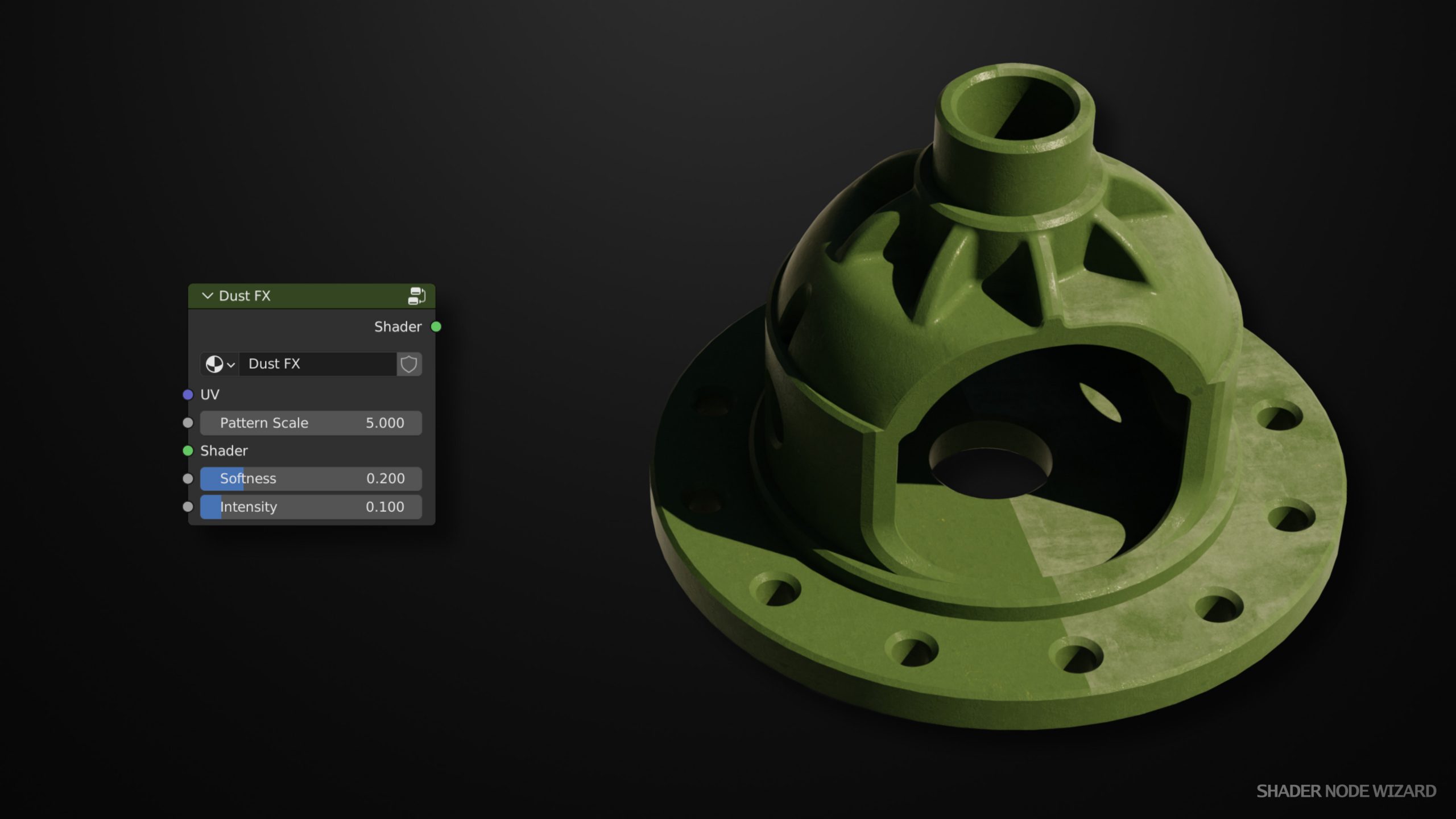
This is a quite simple to configure effect. It just adds a grayish layer on top of the incoming Shader. The node uses the world normal to calculate faces where dust would stay. Softness controls the edge of this area. Intensity controls how intese the dust is visible. The Pattern Scale controls the scale of pattern inside the node, which is used to affect the raw mask. As always, hit the E-Key when the node is selected to choose a different mask texture.
Quick Materials
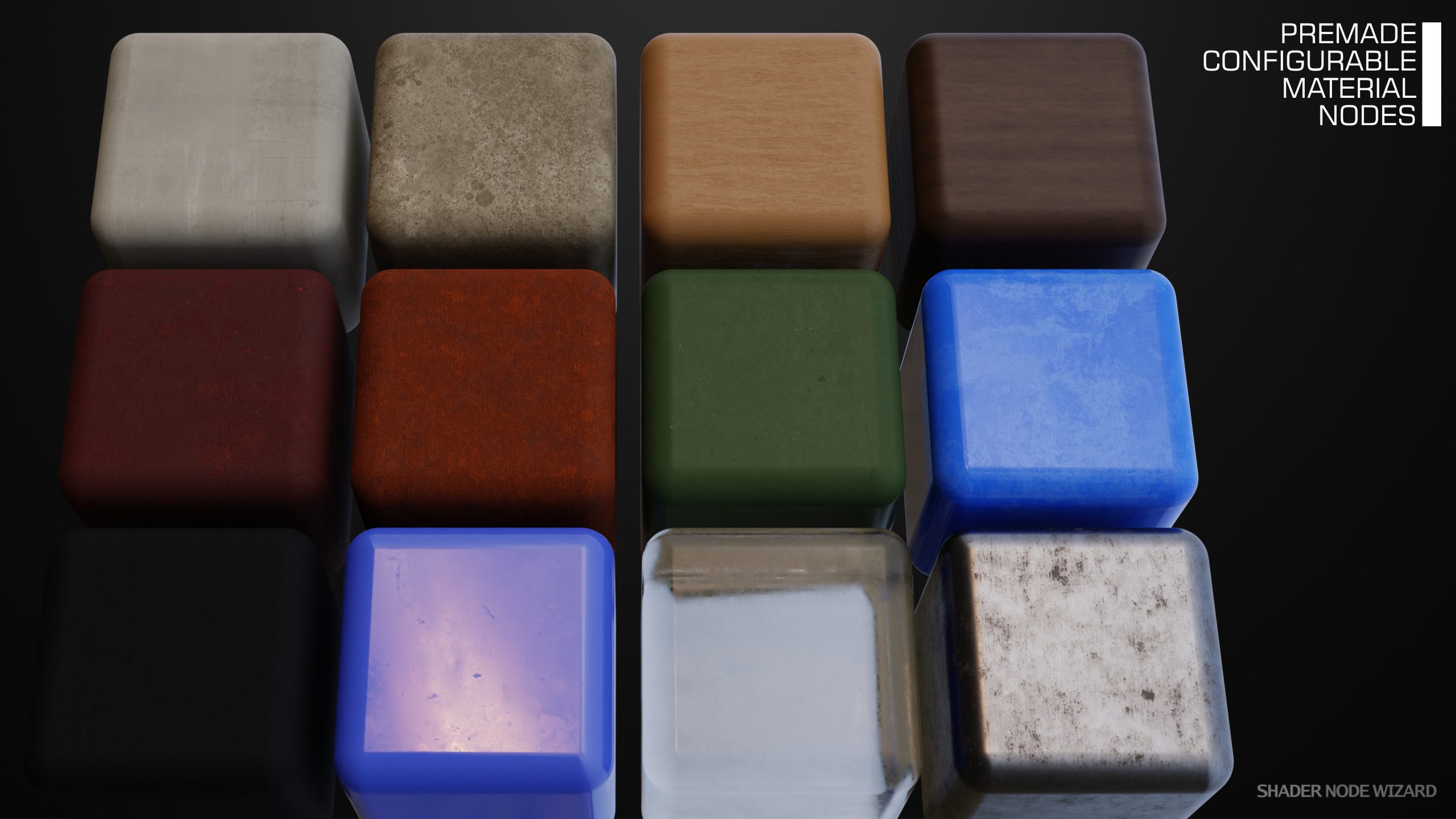
Shader Node Wizard ships with some common, quickly to apply and VRAM friendly Materials. Each just uses a single Grunge Map (except Plastic, which uses two). Every Material has Input Parameters to tweak the Material to your needs. So instead of starting with an Principled BSDF, start with a quick Material.
As with most SNW nodes, hitting the E-Key when the node is selected, let’s you choose a different map.
- Rubber: High roughness and with dents from a grunge map.
- Plastic: High specular, micro-dents from one grunge map and roughness from another, and of course, the color can be controlled.
- Glass: Optimized for less fire flies (all except the camera is just transparent) and with a roughness map, so the glass may look used.
- Metal, Rust, Paint, Conrete and Wood: All these materials are pre-extracted data from PBR sets with a grunge map that controls the surface structure. Controls are identical to those of Grunge maps plus adjustments to the materials colors.
Tool Nodes
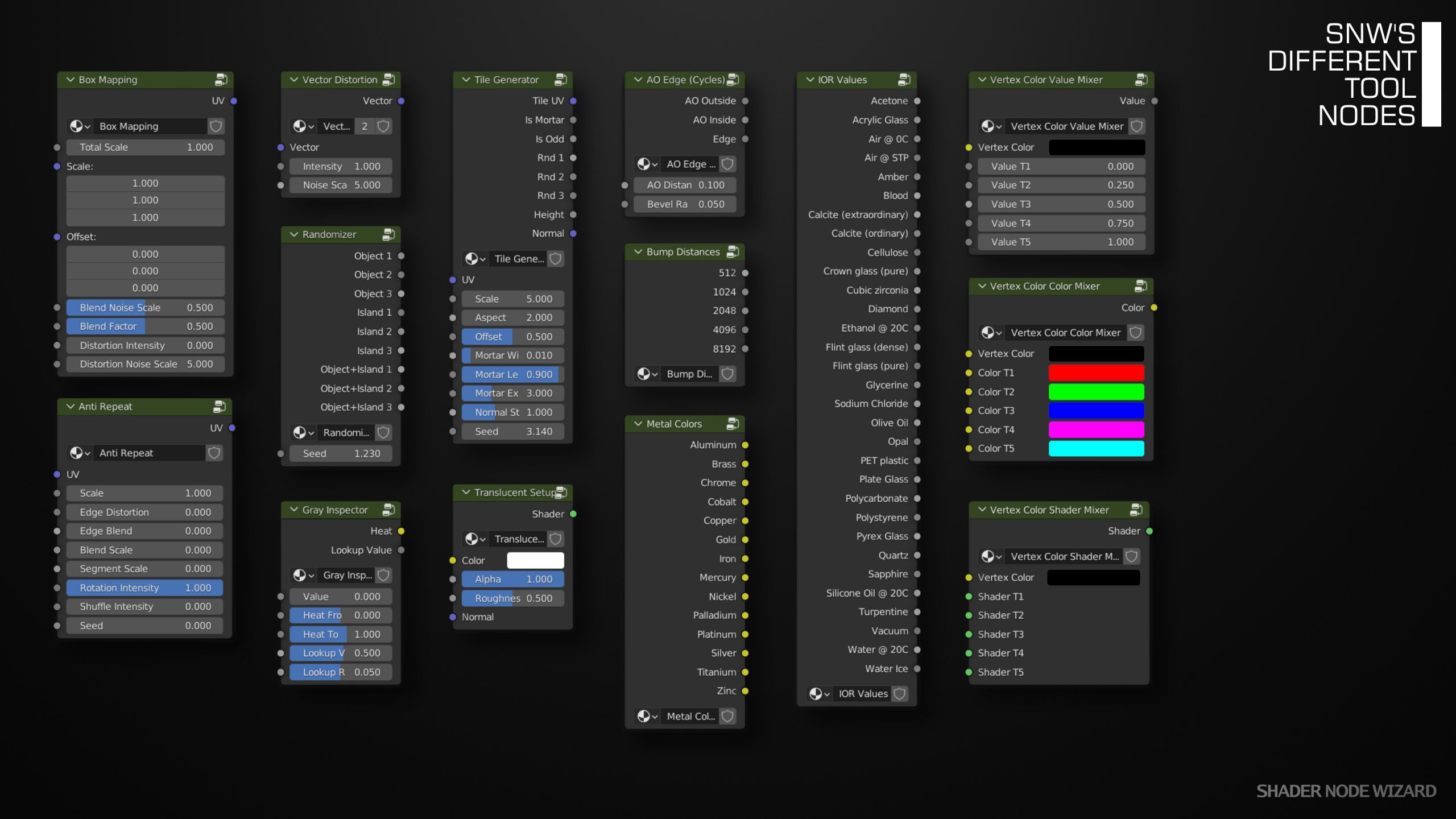
Short Description:
- Box Mapping – Very handy to quickly map a Texture to an Object. Similar to the BOX-Mapping from the Image Texture Node, but maps each Texel depending on the Normal to one Direction. In Slope Areas, a Noise Texture is used to Blend between Directions. Works well in Cycles, but requires some tweaking of Blend Noise Scale in Eevee.
- Anti Repeat – Useful to hide repetition of Textures. Adapted from Erindale, enhanced by a Shuffle Input. So when using Shuffle without Rotation, this works to a certain degree for patterns like Bricks too.
- Vector Distortion – As the name says, distorts a Vector with Noise. Low Noise Scales are useful to scramble UV positions (e.g. geometrical Patterns), High Values create a Texture Blurring Effect.
- Randomizer – Uses the Random Per Object and Random Per Island (Cycles only) feature, but triples the randomness by passing the values through a White Noise Texture plus adds Seed.
- Gray Inspector – It’s sometimes hard to estimate values of Gray Patterns in 3D View. By plugging this node between the Gray Emitter and the View transforms the Values into a Heat Map styled view or highlightes a specific gray value. Simple, but very effective.
- Tile Generator – Similar to the Brick Texture from Blender. Creates a UV-Map for every Tile and creates a Normal Map with Tiles and Mortar. When used with Box Mapping, play with the Distortion Controls to create inaccurate Tile Edges!
- Translucent Setup – When working with Leaves or Grass, this is the correct Setup.
- AO Edge – This can be used to see the AO Edge Map Live in Cycles. Useful to find AO Distance and Bevel Radius, but Baking should be finally used.
- Bump Distances – The Distance Parameter from the Bump Map Node is an important factor creating Normal Mapping. This Node Outputs the correct Distance for common Texture Sizes (Texel to Texel Size).
- Metal Colors – Typical Metal Colors.
- IOR Values – Outputs the IOR Value for different Materials, just plug the correct one into the IOR Input of the BSDF.
- Vertex Color [Value, Color, Shader] Mixer – See Vertex Color Workflow.
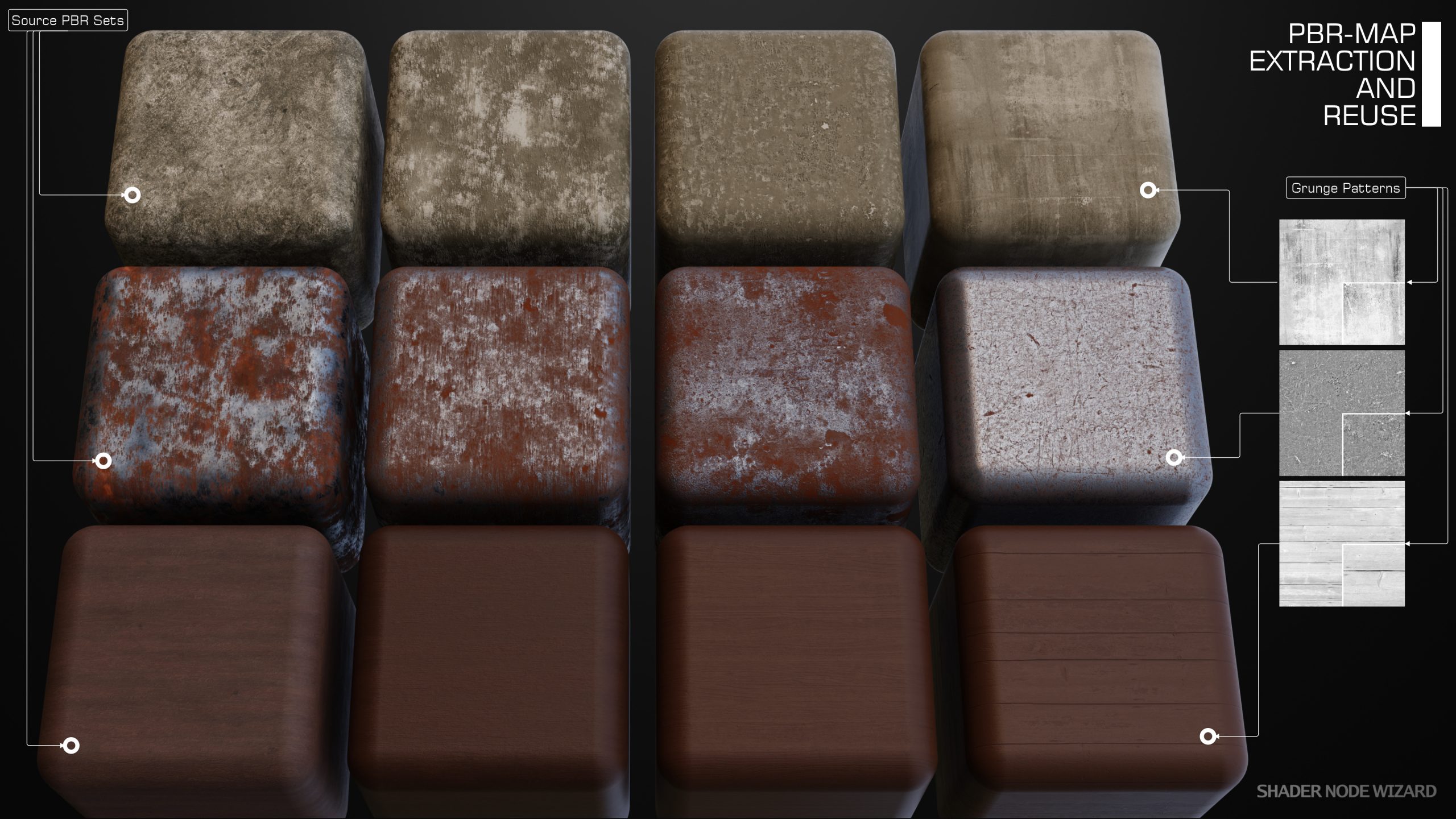
PBR Extractor
The PBR extractor can be compared to tools that extract the most present colors from an image. In reality, this is how this tool started. I was in need to extract some typical rust colors for a promo shot for Shader Node Wizard. Than I experimented with this and PBR Extractor is the result. I found out that just the colors is not enough and even the amount of each color is important. So I developed this tool which extracts metallic, roughness and specular values too.
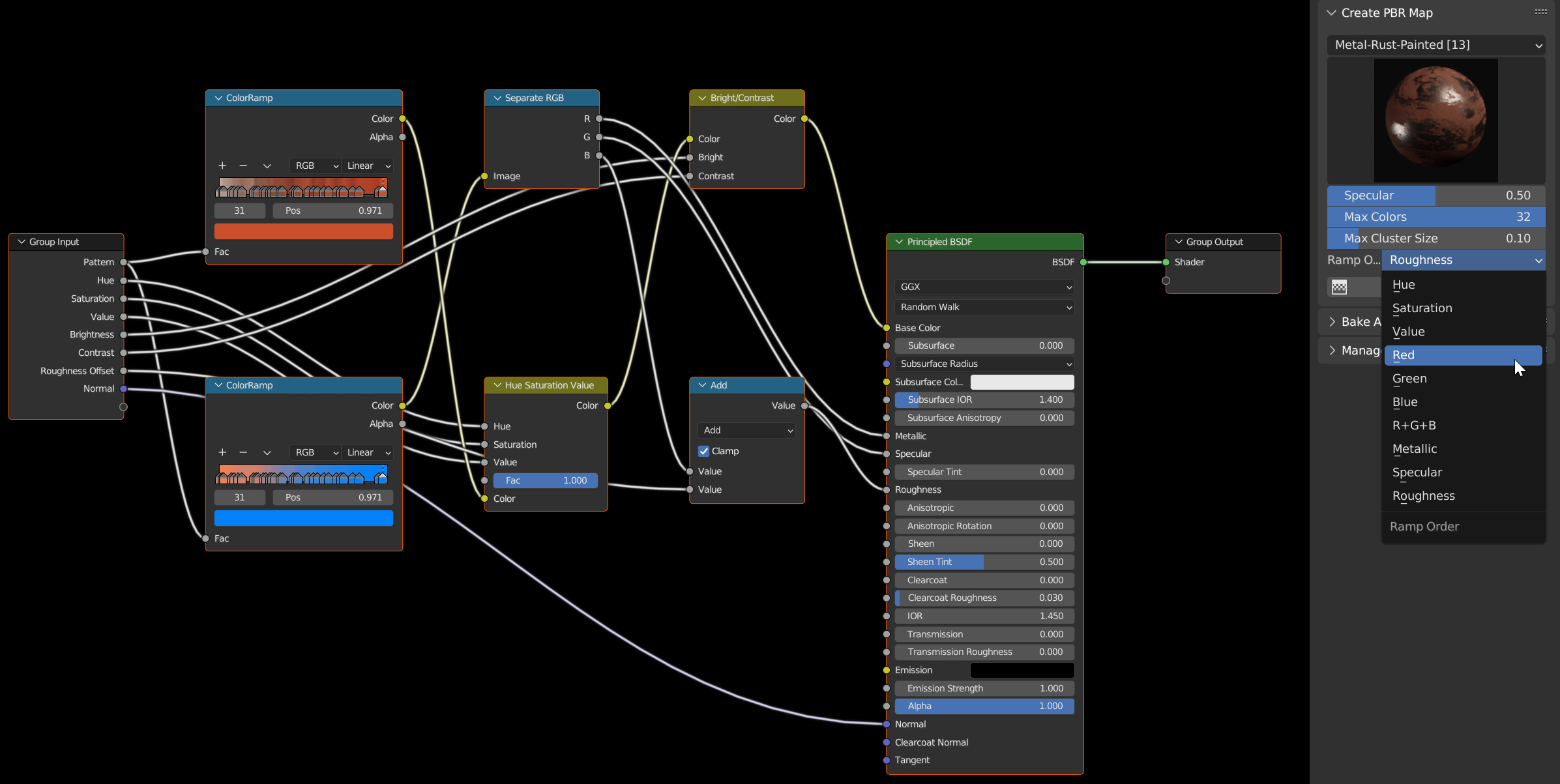
You just select a PBR set in the upper part of the panel and hit Create Map. Thats essentially it, the node on your mouse can now be placed in your node tree. The image above shows what’s inside this node. Just two color ramps, one from the RGB-data, the other one metallic, specular and roughness. If one of these channels is not available in the selected PBR set, the respective default value can be adjusted just below the template icon. In the case above, specular image is not available, so the extractor uses the default 0.5 from the slider. Just adjust it there. Max Colors may reduce the entries in the color ramp, but there’s really no need, more info, better result. Max Cluster Size adjusts the largest space between two entries in the color ramp (if possible). The extracted requantizes recursively until this value has been reached (up to a limit to prevent infinite recursion). An important setting is the Ramp Order. This decides how the extracted data is ordered in the color ramp. Experiments have shown, that roughness gives the best results. But feel free to experiment with this.
The generated node itself just outputs a static color. You need to have at least a grunge map connected to both Pattern and Normal input to create a copy of the original PBR set.
Mask Generator
The mask generator is used to bake (or update) AO and Edge mask for the current selected mesh into the RGB channels of a single texture. It than allows the create the respective node and drop it into your node tree.
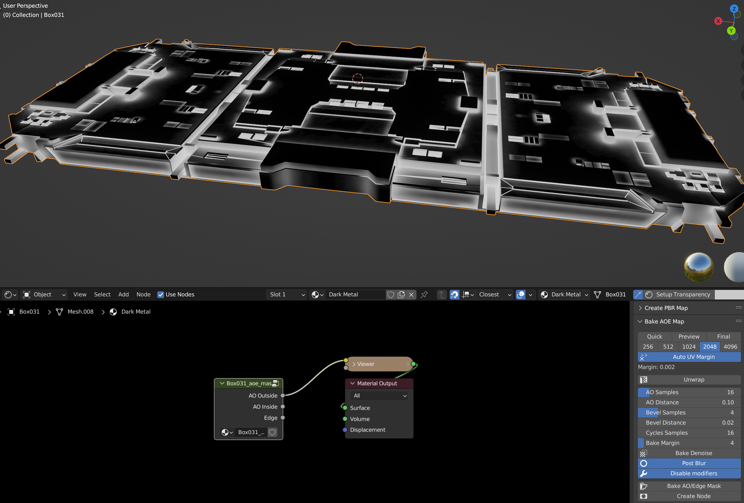
- Quick / Preview / Final: Quickly switch between different presets.
- Resolution: Map resolution of the bake map, the larger, the better. Please note: If you pack the texture and later update the map with a different resolution, this might fail. Haven’t found a good solution yet. Otherwise you can always switch to a different resolution and hit Bake AO/Edge Mask to update.
- Auto UV Margin: If enabled, the margin for UV unwrapping is automatically determinated from selected resolution and Bake Margin setting below. Otherwisey ou get a slider to adjust it. If automatically is enabled, the calculated value is visible just below (0.002 in the image above).
- Unwrap: Unwrap the current mesh, creating or updating an UVMap called UVMap SNW. Click this if you want to re-bake the mask and your model has been changed.
- AO Samples & Bevel Samples: Samples set to the AO and Bevel node when baking the mask.
- AO Distance and Bevel Distance: Distance in world space from edge if the mask baked.
- Cycles Samples: Samples used for baking.
- Bake Margin: Space in pixels filled to reduce visual artifacts at UV edges. Refer to Blenders manual for more details.
- Bake Denoise: If enabled, the denoiser is active when baking.
- Post Blur: If selected, the baked mask will get a fast blurring as post process.
- Disable modifiers: If selected, modifiers will temporary disabled during render. Especially the bevel modifier will have a massive effect on the edge output.
- Bake AO/Edge Mask: Bakes the Map with the settings above.
- Create Node: Create a node like in the image above which has AO Outside, AO Inside and Edge outputs. This is hidden until the map is baked.
Typical workflows:
- First time creating a mask: Unwrap -> Bake AO/Edge Mask -> Create Node (and drop this in your tree).
- Just modified bake settings: Bake AO/Edge Mask
- Update mask after modifying the mesh: Unwrap -> Bake AO/Edge Mask.
Tools
Material Assigner
Quickly assign materials from the current scene to selected objects or to certain faces.
In Object Mode, hit the D-Key to show up the pie menu and select the material you wish to assign to all currently selected object. All current materials these objects have are removed from the object and the selected material is assigned.
In Edit Mode, hit the D-Key as well to select the material to assign. SNW will eventually add the material as slot to the respective object (if not already there) and assign it to the selected faces. These works well if multiple object are edited at that moment.
The New Material option, which is the first entry in the selection list, does what it says. It creates a new material and assigns it like described above.
Material Replacer
This feature is located in Shader Editor side panel. In the first box, select the texture you want to replace and in the second box, the new one. Upon applying, all occurrences in all selected objects where replaced. The replacer takes care of objects with multiple material slots and just replaces the material in question, leaving the other slots untouched.
See Material Assigner and Replacer in action:
Header Menu Tools
The header menu contains some shortcuts, which are very handy.
Frome left to right:
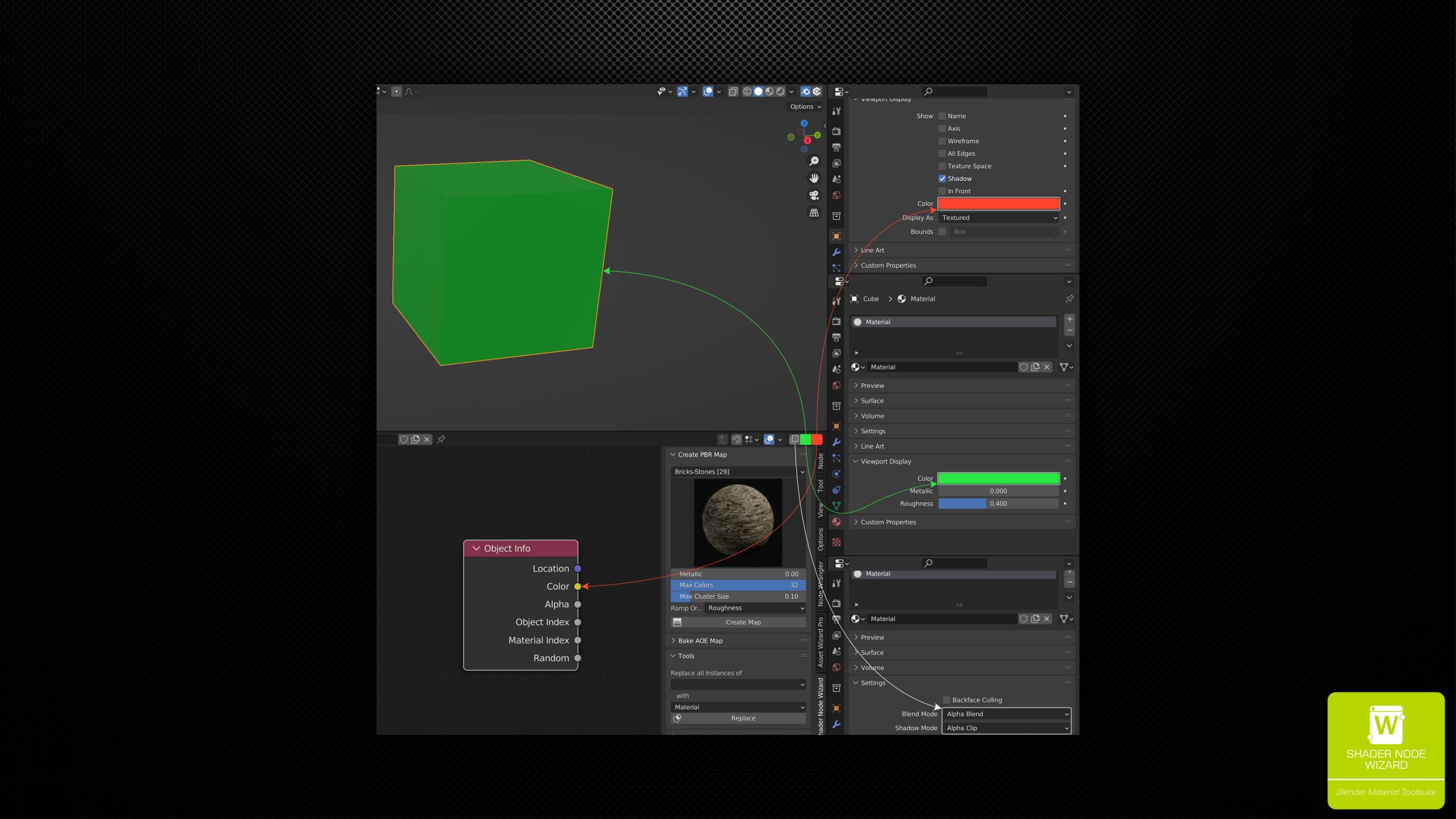
- Eevee Transparency Fix: When editing transparent materials, Eevee shows them opaque by default. This can be adjusted with material settins shown in the right lower corner. Simpler with SNW. Just hit this button to set Blend Mode to Alpha Blend and Shadow Mode to Alpha Clip for the current material.
- Material Viewport Color: This is the color the material is shown in Solid Mode. You can quickly adjust it here (e.g. using the color picker), so get a roughly overview of your scene in Solid Mode.
- Object Color: Very useful property which is available from the shown node. Use it to have a object specific property in your tree. (I’ve used for painted metal, using always the same shader but with object specific color, see image below).
Painting
Painting was added to version 1.1. It is designed to work well with the the IM and FX images (see documention above).
Hitting the E-Key with an IM or FX Image node selected either starts painting mode or switches to the respective image, taking the UVMap into account. Another option is to use the Painting Controls above the PBR Extractor in the side panel. From there you can switch between images in the current tree and exit painting (which can also be done using typical Blender controls).
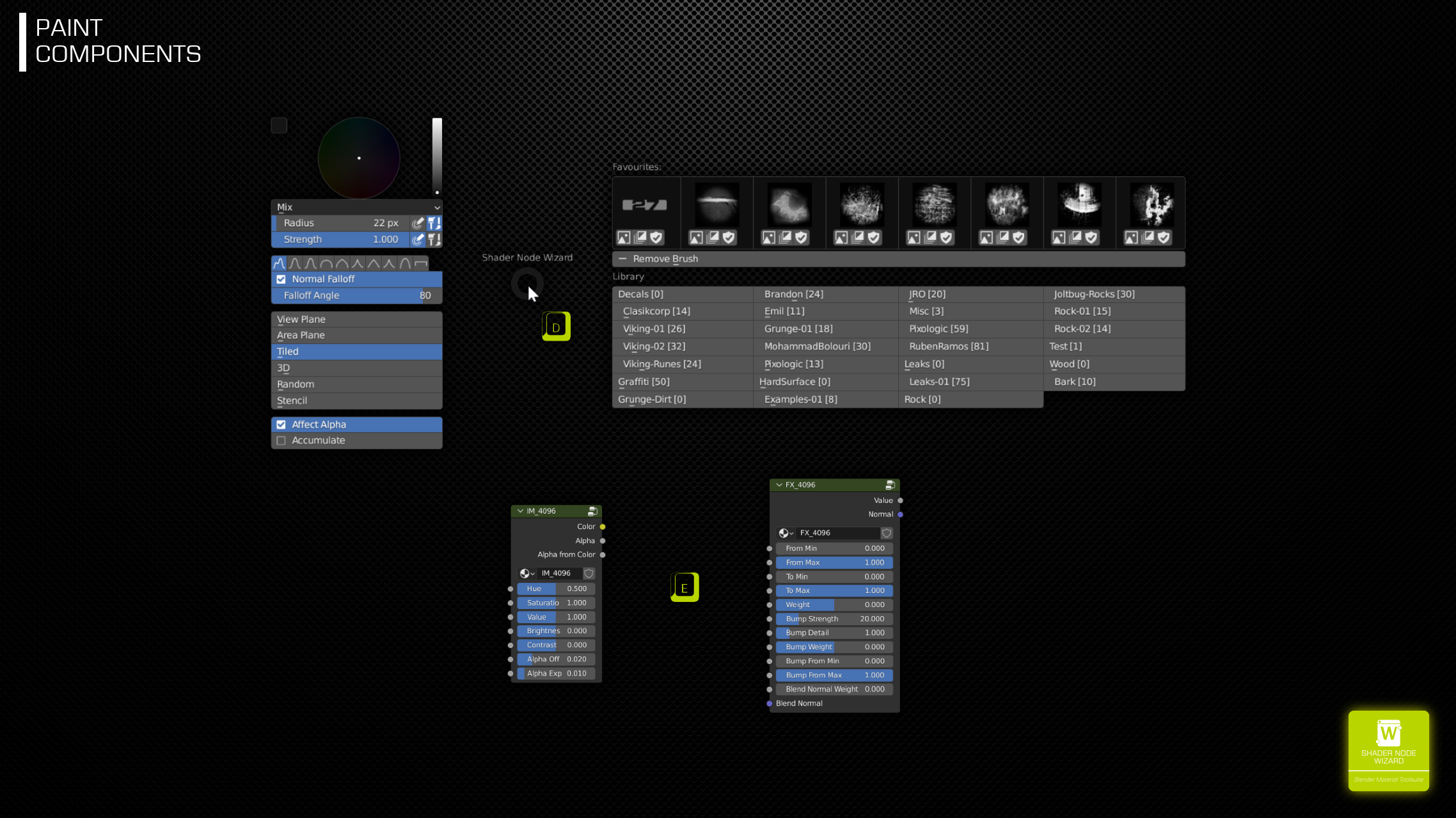
Independent to IM or FX Images, the Painting Pie is always available when in Texture Paint mode. Just hit the D-Key to open it. The left side contains some of Blenders settings targetted to texture painting. You can access them from properties panel or the tools bar too, but the pie contains the most important one (in my opinion).
The right side allows selecting a brush texture to paint with. Selecting one is done using the first or second button below the brush. The leftmost button selects the button in sRGB color space, which should be your first choice when painting to IM images. The second button is more targetted to FX images, as it sets the brush in Non-Color mode. Upon selection, the Image Aspect operator from Blender is automatically applied, so your brush will have the correct aspect ratio.
The third item in this control row is the favourity toggle. When clicking a non-favourite, this brush is added to the front of the favourites row, which is persistant, even when restarting Blender. You can have up to 8 favourites. This limitation is just for UI reasons and may be subject to change in future versions.
The recent row is updated automatically when selecting a brush. This list is purged when exiting Blender.
Installation
You get two .zip files from the download location. One file contains the grunge textures. Just unzip them into a separate folder. You will have to add this (or better it’s parent folder) as Grunge Texture Folder in the preferences.
The second file contains the plugin. Install it as other plugins. In Blender:
Edit > Preferences > Addons > Install
Than enable it. Add your Grunge and PBR folders as described in the following section, so all features of the Addon are available.
Preferences
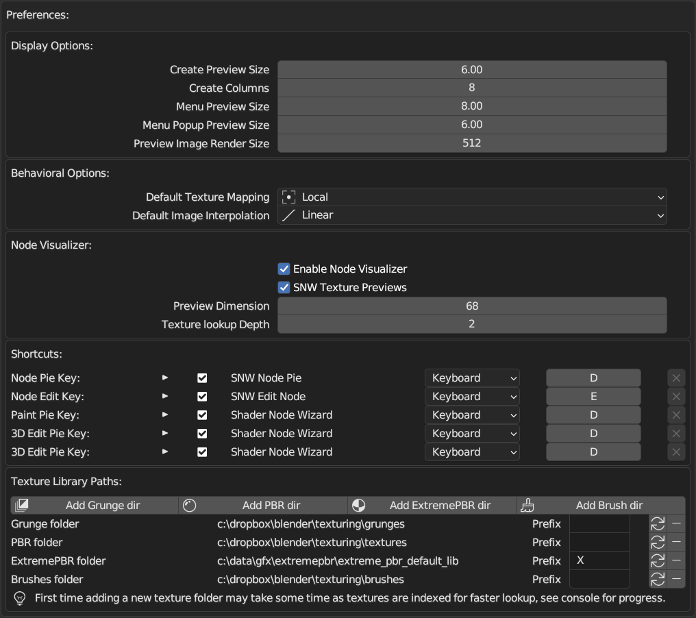
- Display Options: Settings for visualization in Blender.
- Create Preview Size: Scaling of images shown when creating PBR or Grunge Setups
- Create Columns: Number of columns when creating PBR or Grunge Setups
- Menu Preview Size: Scaling of images in Side Panel
- Menu Popup Preview Size: Scaling of images when selecting from Side Panel
- Preview Image Render Size: Image Dimension when rendering a Preview for a PBR Set or Grunge
- Behavioral Options: Defaults when creating Node Setups.
- Default Texture Mapping: Which mapping to set when creating a new PBR or Grunge Setup
- Default Image Interpolation: Which Texture Interpolation is used by default when creating a Setup.
- Node Visualizer:
- Enable Node Visualizer: Enable showing texture previews above Image Texture Nodes and several Node Groups. See here TODO LINK
- SNW Texture Previews: If a Node Group can be identified as SNW Node, the Preview of this Setup is preferred instead of single textures.
- Preview Dimensions: Size of the images shown above Nodes.
- Texture lookup Depth: Recursive levels to search Node Groups for textures.
- Shortcuts: Hotkeys to several features.
- Node Pie Key: Show Pie Menu in Shader Node Editor
- Node Edit Key: Key to press to open the options Dialog for several SNW Node Groups
- Paint Pie Key: Show Paint Pie in 3D View (Paint Mode)
- 3D Edit Pie Key: Opens the Pie in 3D View (Edit Mode) to manage Vertex Colors. See here.
- Texture Library Paths: Manage PBR, Grunge and Brush folders.
PBR, Grunge and Brush directories
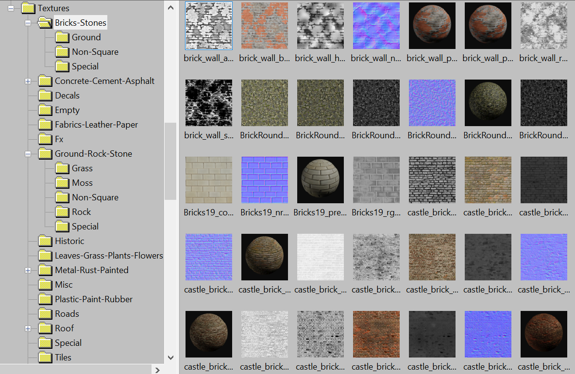
These folders types were scanned and visualized recursively. Just put your image files into these folders.
PBR
SNW tries to find sets of textures by their names. Texture files that belong to one set must be in the same folder. A typical folder should look like this:
Grunge
Grunge files are just single gray images. There’s one specific case to reduce VRAM usage, which is used by the supplied Grunge files that ship with SNW. In this case, 4 gray images are packed in the R, G, B and A channels of an image file. To allow SNW to detect these images, file names must have the postfix ‘4g’, e.g. snw-common-pack1-4g.png.
Extreme PBR
This is a special case for owners of the ExtremePBR Blender Addon. Just select the root folder. Starting from Version 1.2, ExtremePBR Vault folder structure is supported as well. SNW automatically recognizes different texture resolutions.
Upon adding, Shader Node Wizard scans and indexes the files once. For every texture, a hash is created to uniqly identify it (in case of PBR sets, the diffuse channel file is used). This is used for the editing feature, to select the correct category and texture in the UI controls. Hashes are stored in your home folder, sub-folder .shader-node-wizard/.
Brushes
Starting with version 1.1, painting features have been added to SNW. Here you can select one or more folders that contain paint brushes, offering the same category structure support as the other one. You can than select brushes in the painting pie.
The Prefix can be used to separate libraries in the category selection. I’ve used ‘X’ for the ExtremePBR library, so all categories from ExtremePBR are placed at the end, but still ordered alphabetically:
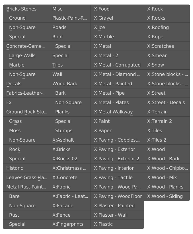
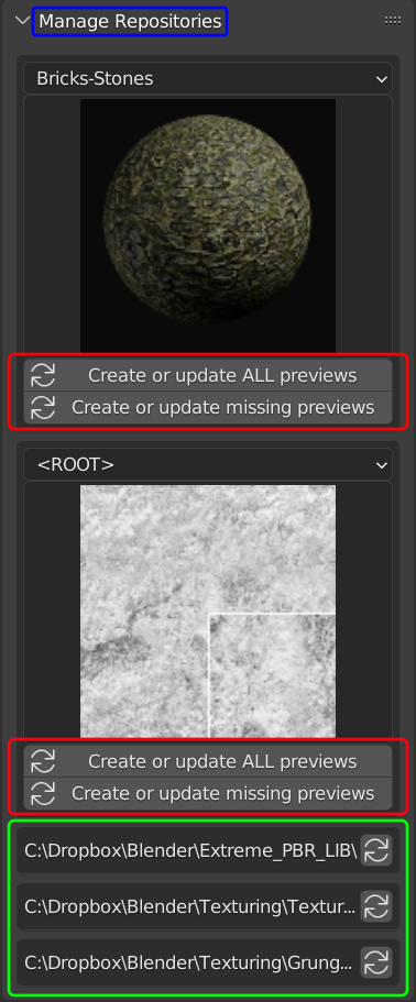
The Circular Arrow and the Minus buttons close to Prefix fields are used to rescan or remove a library respectively. Rescan is useful if you copy new content to your libraries and want to use them without restarting Blender. Rescanning is also possible from the side menu in the Shader Editor (green highlight in the Image below).
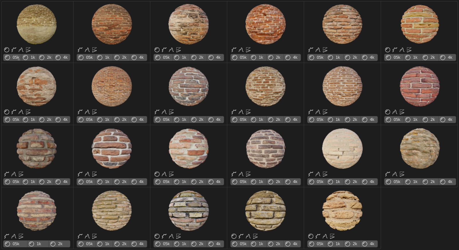
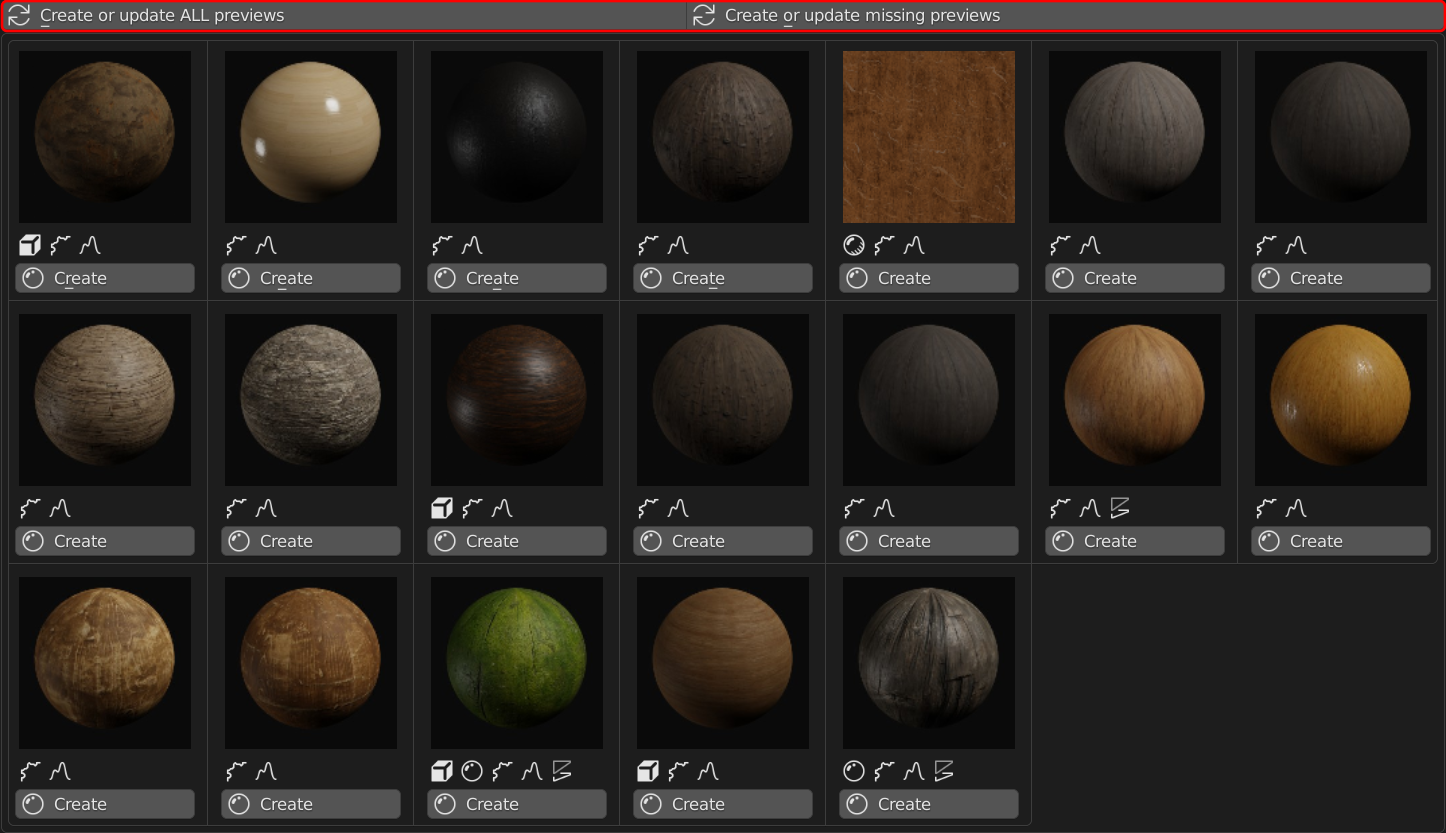
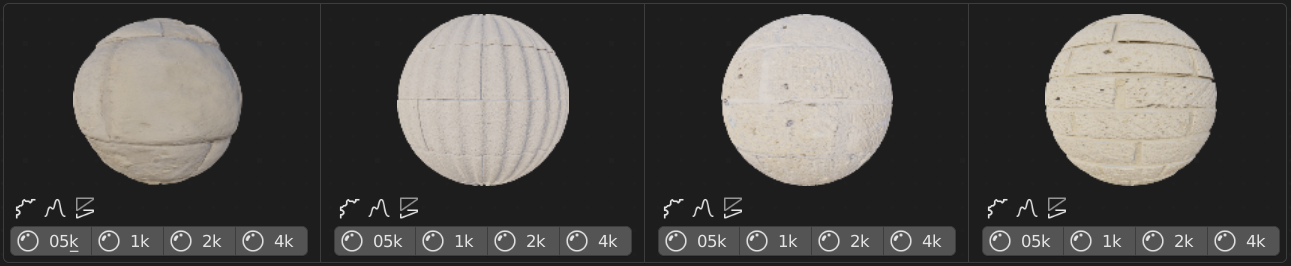
Preview Thumbnails
All PBR Sets and Grunges were visualized using Preview Images. If no preview image is available, either the diffuse channel is shown, or in case of Grunge textures, the gray image itself.
This has two side effects. The original image is loaded much slower, as it is usually a larger file. Especially in case of PBR, the diffuse image does only partially show the real look of the Set.
To create all or missing Preview Images, you can do this for the selected category by clicking on the highlighed buttons in the side panel in Material Shader Editor (hidden by default).
Another option to do this is at the top of the creation Pie, see below.
Changelog
1.3
- Many texture mapping features in the Edit Dialog. See here
- Material Assigner in object and edit mode and Material Replacer in tools panel. See here
- Shader Node Editor header menu now contains Eevee transparency fix, material color and object color. See here
- Support for non-latin path- and file names
- Much faster startup due to repository caching
- If Asset Wizard Pro is installed too, the Main Pie menu shows a switch toggle
1.2
Support for ExtremePBR Vault folder structure added. Due to a customer request, SNW now detects and support the folder structure of the ExtremePBR Vault library. To support multiple texure resolutions, both create and edit dialogs has been enhanced to allow a selection there (if more than one resolution is present).
The preferences got a visual overhaul as well. In addition, you can assign own hotkeys for pie menus now.
1.1
Paint features added:
- Main Pie enhanced for more control in image creation
- IM and FX images are available, which create different node group that suite the intended purpose
- E-Key hit on those groups enter texture paint mode and/or switch to this image (including managing to set the correct UVMap)
- D-Key in 3D View while in texture paint mode opens the Paint Pie with brush controls
Vertex color Pie added:
- Removed the header located vertex paint features and moved to a separate Pie Menu, which opens in 3D View when in edit mesh mode
- Random per island feature added
1.0
Initial Release